Structural load test

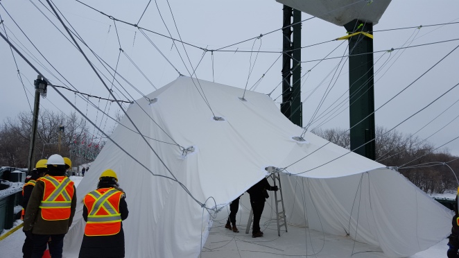
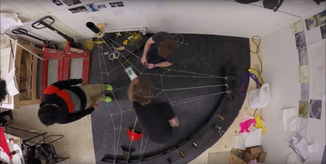
During a particularly cold week in mid February (-20C to -30C) we were able to carry out the structural load test we had been hoping to conduct for this project.  The aim was to create a sheet of ice on the outer surface of the fabric and to release the cables to see if the folded geometry would support the loads of the ice and snow.  
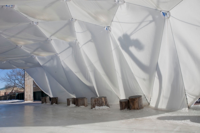
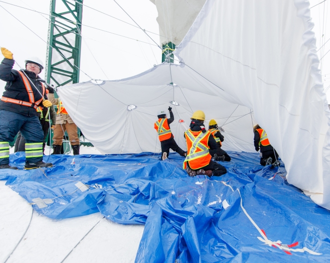
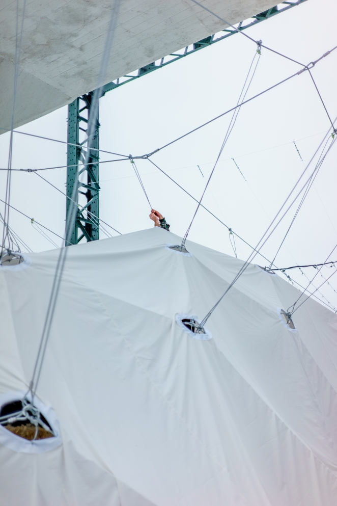
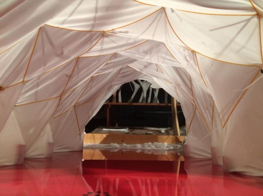
Over the course of two nights during that week we applied 28 coats of water and were successful in creating an ice sheet with a varying thickness of ¼” – ½”.  On the morning of the third day we arranged to loosen the turnbuckles and slowly release the tension support of the upper cables, thereby releasing the support of the connecting “grab cables” that was pulling the fabric and interior cables into form.  Despite enormous cracking sounds and popping that was coming from the shattering ice that had adhered to the steel cables from the spray operation, the form of the fabric and ice shell did not budge.  Once fully released from the supports of the cables, it was clear that the building had not moved and it was fully supporting itself; Fabrigami was officially a free-spanning fabric reinforced ice shell structure spanning 28’ (wide) x 38’ (long) x 12’ (tall)!

12 (1)3 (1)4 (1)5 (1)6 (1)

Site Construction

After the mass redesign to accommodate a completely new site; fabrication, construction and assembly was in full swing. With helping hands from 0812 Building Solutions the upper cable net was set into place and tightened to temporarily take up the weight of the future iced structure.

Next step was to have all hands on deck for the ‘Big Pull’. Lifting the building into place was always a part of the plan for site construction, we had been imagining it would be undertaken through an inverted marionette technique. We began by first establishing the position of the 2D fabric pattern relative to the upper cable net. For every hole in the fabric there was a 3/8” cable that corresponded to a U-clamp on the upper cable net. Once all 28 cables had been draped through their U-clamps they were fed back through the hole in the fabric. This allowed for all 17 individuals on site to begin pulling at the cables, resulting in a lift of the fabric. Having a uniform tensile force on all the cables helped direct the structure into its final form and allowed for a truly collaborative install. The last important part was to reach through each hole and clamp the cable to itself, giving the structure a form of permanence that would allow for icing. Yet still give us the freedom to losing the upper cable net to test the loading capacity, once iced.

Inherent to the construction and design detailing of the upper cable net structure was a wide tolerance range. Since we were unable to mimic the cable material and weighted iced fabric in the digital model, it was critical we had the opportunity to adjust or remove sections of cables if need be. Ultimately turnbuckles proved to be our best friend in this construction. They allowed us loads of room to adjust, tighten and release the fabric structure when we needed.

23578 (1)46

Prefabrication

Working together, for 10 days at the beginning of January, the team prefabricated several elements of the design in advance of the site fabrication. The components included: the assembly and integration of the cable loops into the fabric, the cutting of the steel cables and the assembly of the cable structure.

Work was done in the FABLab, as well as in the largest room available in the Faculty – the main Centerspace of the John A. Russell building; where a tarp was laid down to accommodate the flat assembly of the steel cable system and the connection to the fabric.

The fabric panels were pre-sewn by a manufacturer in the city. The fabric was then laid out flat in order to locate and position the holes through which the upper cable and lower cable structures would connect. The 8” diameter holes were reinforced with steel cable loops sewn into place. The second component was the fabrication of the cable net. This included the cutting of specific lengths of cable, crimping the sleeves and finishing the ends with thimble loops. These lengths were then joined together at specific locations with a quick link. The intention behind the prefabricated cable net structure was to create a system in which the length of the individual cable links were fixed, therefore having the advantage of being relatively easy to assemble and erect on site. Due to the possibility of errors in the calculations and manufacture, and the desire to tension the net properly, a number of turnbuckles were also incorporated in specific locations, enabling the length of some of the cables to be adjusted on site.

The fabric and the cable net were connected together with small u-clamps to create the Fabrigami structure, prefabricated and ready to head out to the site.

FABRIGAMI_14_WH2016 (1)FABRIGAMI_12_WH2016 (1)9 Kim_Collaboration (1)8 Kim_Collaboration (1)

Site change and redesign charette

This year’s winter temperatures were unseasonably warm causing the Assiniboine and Red rivers to freeze at a much slower pace than previous years.  As a result we needed to select an alternate site to provide both solid grounding as well as site conditions that would allow us to create a strong cable net structure to raise our fabric shell.

 
Adjacent to our initial site there is a converted train bridge that has since become a pedestrian pathway for the Forks Park. The bridge was designed with a large concrete counterweight which would allow it to be lifted allowing ships to pass underneath.  The existing steel framing and concrete structure acted as excellent anchor points for us to design a new cable system.  Because of the preliminary research in how to design a cable net system and develop an origami structure that was able to be shaped to suit a unique site, we were able to adapt to the new site constraints in short order.  The building form came about out of a negotiation of the skating path and walking trail that moved through the building as well as the new geometric boundaries set up by the new overhead cable net. The final building design proposed the creation of a 28’ wide, 38’ long, and 12’ high space enclosed by a folded cotton (96%) and spandex (4%) blended fabric origami structure.

Screen Shot 2016-04-13 at 9.20.01 AMScreen Shot 2016-04-13 at 9.20.16 AMNew structure Intent_layout

Cable/Fabric Formed Structure Test

Today we were able to construct our first successful cable guided fabric formed origami pattern.  The structure is a modified barrel vault that possesses load bearing (spanning) capacities and also seeks a transition from a larger scaled opening at the front to a smaller opening at the back. This will help with fitting the structure underneath the sloping cable net above. As can be seen here, we have decided to forego the cable guided valleys as sharp transitions for a gravity induced sag which produces a catenary curved section in the valleys which will (in theory) give us a form capable of transferring load paths more efficiently in each diamond shaped “beam” spanning from node to node. Once iced, these beams will become the units that construct the spanning arches over the interior.

IMG_6149IMG_6150IMG_6155IMG_6159

Time Lapse Video – New Cable Pattern

Using optimal stress flow patterns developed by Caitlin Mueller and her team at MIT we tested a new cable pattern linking three main anchor points on the site (two areas along the shoreline and the lighthouse). By distributing the loads of the fabric structures between these three areas this cable pattern allows us to distribute the load evenly along the cables, achieve enough stiffness in the cable net to pull up to with sufficient tension, as well as create lateral stiffness (from the horizontal funicular outer most boundary cables) to be able to pull at angles down to the ice. This video shows a time lapse of us constructing the cable that onto our 1:10 physical model.

https://drive.google.com/file/d/0BwGcnoseMbpxOTNzQlNweWtGMW8/viewgopro

November 24 – Cable Net Design

Today we began to explore possible cable arrangements to connect the lighthouse (the black pole) to the surrounding water pier mooring posts (screws around the perimeter shoreline) on our 1:10 scale physical model.  This new patterning study will allow us to explore the creation of several smaller buildings as an alternative to the singular larger structure we have been studying to date.

cable net

Fabric formed wax folding test

This week we attempted to study how the folding patterns developed through a tensile net using “ridges” and “valleys” might be further explored by replacing the sharp “valley” folds (previously created by downward pulling strings) with curved valleys created by the weight of liquid wax (to mimic the influence of ice on the fabric).  The model we used was the same interlaced diamond pattern that we had used previously that we now layered that with a synthetic/natural fiber blended fabric.  Using a heated modeling table, paraffin wax was used to simulate liquid water (pre-freezing). Magnets were used to hold down the fabric pattern to the table, while strings attached to the frame around the table introduced the tension necessary to achieve the vaulting form.  Once formed and the liquid wax was applied to the fabric layer, the heat was turned off to rigidify the model.

The resulting model showed some deformation of valleys caused by the wax, but some areas were less obvious due to the scale of the structure in comparison to the size of the folds in the pattern and the inability to create even and precise tension field on the cable net structure pulling up.  In addition, due to the overall stiffness of the fabric and the number of facets on the vaulting form (causing there to be shallower valleys between the peaks) this model proved difficult to decipher.

The next step will likely include a scaling up of the fabric model on this heated wax table as well as using a pattern that has deeper folds in order to gain a more dramatic topography between the ridges and valleys produced by the tension net.

fabric formed wax test_01fabric formed wax test_02

Physical Origami Cable Model Test 1

The pattern used to create the first origami form was studied to translate the folding of paper to the linking of cables to form the ridges and valleys. In order to do this we proposed that the fabric layer being folded would form ridges through the use of cables pulling from under the fabric, and form valleys through the cables pulling down on top of the fabric. This approach allowed us to divide a standard folding pattern into two separate patterns, a ridge pattern and a valley pattern. In physical form this would allow us to first construct a ridge cable pattern, then introduce a fabric layer and then conclude with a valley cable pattern on the top. The intersections of the valley and ridge patterns would be then coupled through a hole in the fabric.

By using an odd number of spaces between intersection points in the x and y directions, we are able to achieve a continuous woven pattern using a single cable for both the ridge and valley patterns.We first began to test this approach by leaving out the fabric and only building the cable model of the origami pattern. We used posts (screws) on a plywood sheet to weave the ridge pattern and valley patterns and zip tied them together. After attaching leads to each intersection we used the digital model to locate appropriate anchor points and then used a wooden frame to pull the intersections of strings to. The resulting form is shown in the pictures here. Because of the inaccuracies of the construction and the varying tensions in the pulled points the pattern had loose and overly taught areas, but the overall form was achieved as hoped. We will next try to introduce a fabric layer into the this assembly method.


Physical to Digital and Back

Our interest in the direction of this project is to construct a relationship been the digital and physical design process so that one feeds into the other and influences the methods of full scale construction.

In this project we intend to utilize an origami folding pattern with a fabric formed ice sheet. The advantage of using origami as a forming technique is that it has the ability to produce rigid stable forms with shear planes, can be formed using non-stretch materials, and made using non-customized sheet patterns.


In order to do this, we are intending to use high-tensioned cables to form the mountains and valleys in the folding pattern to shape the fabric panel. This process will require a translation to move from the techniques required to produce a folded rigid non-stretch plane (like paper) to a edge formed pattern that guides a non-stretch but pliable fabric plane. To begin this we developed a grasshopper model in order to visualize the folding pattern in real time. This model allowed us to develop a pattern language of “valleys” and “ridges” and to choreograph the forces required to manipulate this pattern through Grasshopper and Kangaroo 2. We are beginning with a simple folded pattern that would create a folded barrel vault (capable of being self supporting with an anchored base). With this test pattern we are attempting to find the mechanical behaviour of the ridges and valleys and the points of intersection which join them. Once this is achieved we will use this technique to allow for the exploration and rapid visualization of other origami folding patterns.

The ongoing intent of the digital script is to mimic the physical properties of the material (cable, fabric) and actions (via construction techniques) being used in this project. This allows for the study of the digital through the representation of the physically built structure. At the present time the grasshopper script only mimics ridged body typologies (such as timber struts or planer faces) and not rope or cable topological forms.